Floor – Heavy Duty – Auto H2O
Heavy Duty Floor Joints
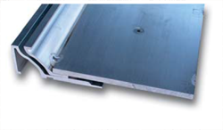
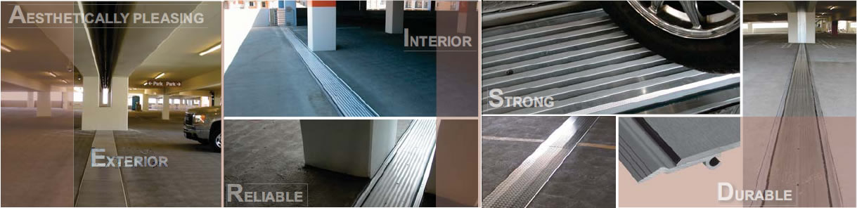
M.H. Powell & Co., Inc. provides a series of seismic expanion joint covers to meet auto load and impacts. These heavy duty floor joint systems are designed to match most structural and design intent.
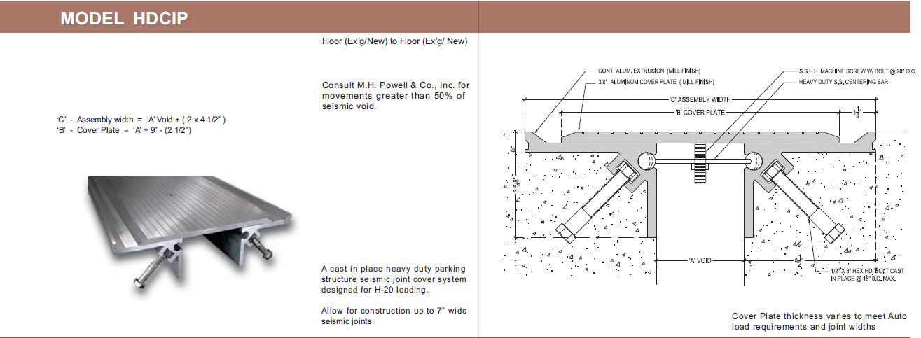
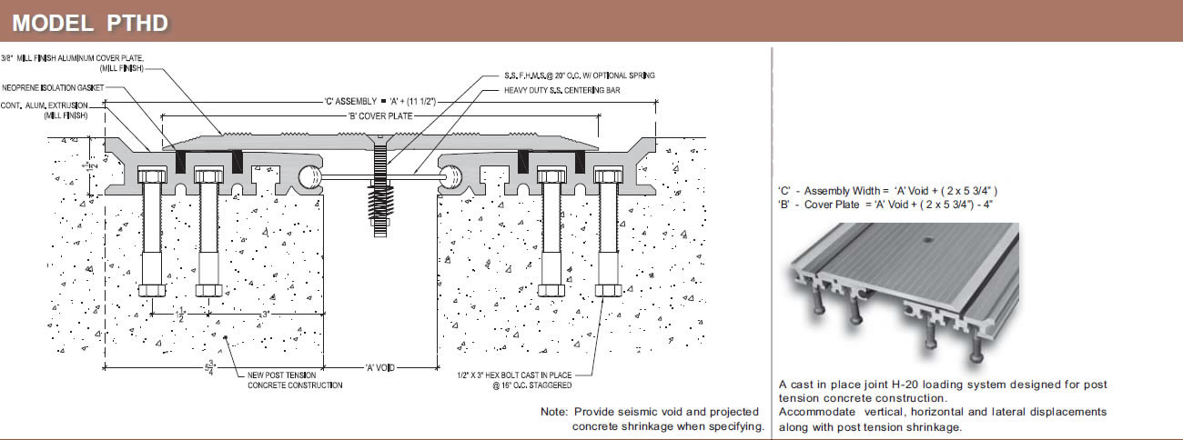
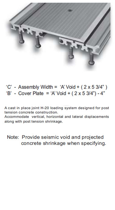
Due to auto traffic and constant heavy impact, the PTHD, PTHDXW, PTHDS, HDCIP and HDEXW models are incorporated with cast in place anchors which allow proper placement in post tension concrete floor systems
This adjustable anchoring system requires project field coordination for proper installation.
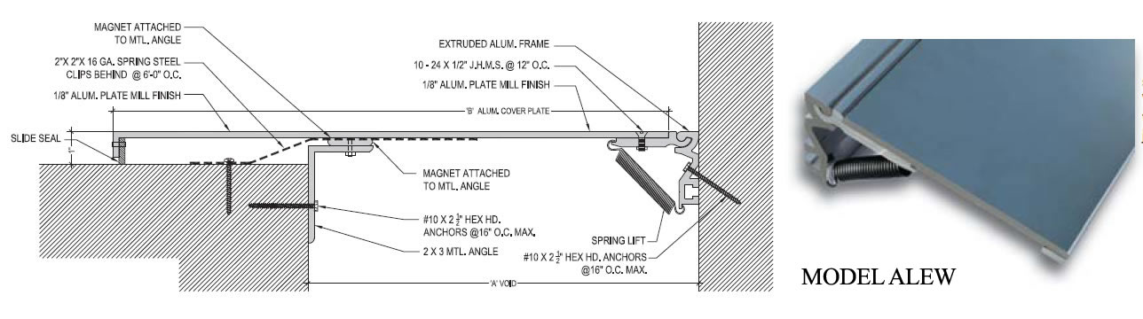
Model BOHD
Model
Installation Guide
Specs
Model

Model WS can be used mainly on flat surface conditions on both walls and ceilings.
Installation Guide
Vivamus fringilla suscipit justo
Aenean dui nulla, egestas sit amet auctor vitae, facilisis id odio. Donec dictum gravida feugiat.
Class aptent taciti sociosqu ad litora torquent per conubia nostra, per inceptos himenaeos. Cras pretium elit et erat condimentum et volutpat lorem vehicula
Morbi tincidunt pharetra orci commodo molestie. Praesent ut leo nec dolor tempor eleifend.
Model WS can be used mainly on flat surface conditions on both walls and ceilings.
Specs
Phasellus non nibh
Non erat laoreet ullamcorper. Pellentesque magna metus, feugiat eu elementum sit amet, cursus sed diam. Curabitur posuere porttitor lorem, eu malesuada tortor faucibus sed.
Duis pulvinar nibh vel urna
Donec purus leo, porttitor eu molestie quis, porttitor sit amet ipsum. Class aptent taciti sociosqu ad litora torquent per conubia nostra, per inceptos himenaeos. Donec accumsan ornare elit id imperdiet.
Suspendisse ac libero mauris. Cras lacinia porttitor urna, vitae molestie libero posuere et.
Model WS can be used mainly on flat surface conditions on both walls and ceilings.
Interior / Exterior Walls & Ceillings – Flat Conditions
| Joint "A" | Model | Max Opening | “B” Cover | Downloads |
| 4"(101.60) | BOHD-4 | +/-50%(2") | 10.5"(266.70) | PDFCAD |
| 5"(127.00) | BOHD-5 | +/-50% (2.5") | 11.5"(292.10) | PDFCAD |
| 6"(152.40) | BOHD-6 | +/-50%(3") | 12.5"(317.50) | PDFCAD |
| 7"(177.80) | BOHD-7 | +/-50%(3.5") | 13.5"(342.90) | PDFCAD |
| 8"(203.20) | BOHD-8 | +/-50%(4") | 14"(355.60) | PDFCAD |
| 9"(228.60) | BOHD-9 | +/-50%(4.5") | 15.5"(393.70) | PDFCAD |
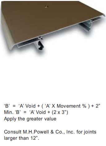
Consult M.H.Powell & Co., Inc. for joints larger than 12”.
Lorem ipsum dolor sit amet, consectetuer adipiscing elit
Model HDCIP
Model
Installation Guide
Specs
Model
Class aptent taciti sociosqu ad litora torquent per conubia nostra, per inceptos himenaeos. Cras pretium elit et erat condimentum
Installation Guide
Vivamus fringilla suscipit justo
Aenean dui nulla, egestas sit amet auctor vitae, facilisis id odio. Donec dictum gravida feugiat.
Class aptent taciti sociosqu ad litora torquent per conubia nostra, per inceptos himenaeos. Cras pretium elit et erat condimentum et volutpat lorem vehicula
Morbi tincidunt pharetra orci commodo molestie. Praesent ut leo nec dolor tempor eleifend.
Class aptent taciti sociosqu ad litora torquent per conubia nostra, per inceptos himenaeos. Cras pretium elit et erat condimentum
Specs
Phasellus non nibh
Non erat laoreet ullamcorper. Pellentesque magna metus, feugiat eu elementum sit amet, cursus sed diam. Curabitur posuere porttitor lorem, eu malesuada tortor faucibus sed.
Duis pulvinar nibh vel urna
Donec purus leo, porttitor eu molestie quis, porttitor sit amet ipsum. Class aptent taciti sociosqu ad litora torquent per conubia nostra, per inceptos himenaeos. Donec accumsan ornare elit id imperdiet.
Suspendisse ac libero mauris. Cras lacinia porttitor urna, vitae molestie libero posuere et.
Class aptent taciti sociosqu ad litora torquent per conubia nostra, per inceptos himenaeos. Cras pretium elit et erat condimentum
| Joint "A" | Model | Max Opening | “B” Cover | Downloads |
| 4"(101.60) | HDCIP-4 | +/-50%(2") | 10.5"(266.70) | PDFCAD |
| 5"(127.00) | HDCIP-5 | +/-50% (2.5") | 11.5"(292.10) | PDFCAD |
| 6"(152.40) | HDCIP-6 | +/-50%(3") | 12.5"(317.50) | PDFCAD |
| 7"(177.80) | HDCIP-7 | +/-50%(3.5") | 13.5"(342.90) | PDFCAD |
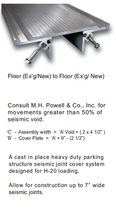
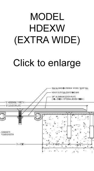
Model HDEXW (Extra Wide)
Model
Installation Guide
Specs
Model
Class aptent taciti sociosqu ad litora torquent per conubia nostra, per inceptos himenaeos. Cras pretium elit et erat condimentum
Installation Guide
Vivamus fringilla suscipit justo
Aenean dui nulla, egestas sit amet auctor vitae, facilisis id odio. Donec dictum gravida feugiat.
Class aptent taciti sociosqu ad litora torquent per conubia nostra, per inceptos himenaeos. Cras pretium elit et erat condimentum et volutpat lorem vehicula
Morbi tincidunt pharetra orci commodo molestie. Praesent ut leo nec dolor tempor eleifend.
Class aptent taciti sociosqu ad litora torquent per conubia nostra, per inceptos himenaeos. Cras pretium elit et erat condimentum
Specs
Phasellus non nibh
Non erat laoreet ullamcorper. Pellentesque magna metus, feugiat eu elementum sit amet, cursus sed diam. Curabitur posuere porttitor lorem, eu malesuada tortor faucibus sed.
Duis pulvinar nibh vel urna
Donec purus leo, porttitor eu molestie quis, porttitor sit amet ipsum. Class aptent taciti sociosqu ad litora torquent per conubia nostra, per inceptos himenaeos. Donec accumsan ornare elit id imperdiet.
Suspendisse ac libero mauris. Cras lacinia porttitor urna, vitae molestie libero posuere et.
Class aptent taciti sociosqu ad litora torquent per conubia nostra, per inceptos himenaeos. Cras pretium elit et erat condimentum
| Joint "A" | Model | Max Opening | “B” Cover | Downloads |
| 4"(25.40) | HDEXW-4 | +/-50%(2") | 14"(355.60) | PDFCAD |
| 5"(50.80) | HDEXW-5 | +/-50% (2.5") | 15"(381.00) | PDFCAD |
| 6"(152.40) | HDEXW-6 | +/-50%(3") | 16"(406.40) | PDFCAD |
Model PTHD
Model
Installation Guide
Specs
Model
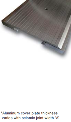
W-Series offers wide range of seismic expansion movements.
Custom designed Aluminum cover plates provide the ability to withstand up to 100% or more maximum seismic joint movement.
M.H. Powell & Co., Inc. is always ready to offer its experienced technical assistance for Architects, Engineers and Builders in designing expansion joint cover systems for project specific conditions.
Contact M.H. Powell & Co., Inc. for further details and assistance.
Installation Guide
Vivamus fringilla suscipit justo
Aenean dui nulla, egestas sit amet auctor vitae, facilisis id odio. Donec dictum gravida feugiat.
Class aptent taciti sociosqu ad litora torquent per conubia nostra, per inceptos himenaeos. Cras pretium elit et erat condimentum et volutpat lorem vehicula
Morbi tincidunt pharetra orci commodo molestie. Praesent ut leo nec dolor tempor eleifend.
W-Series offers wide range of seismic expansion movements.
Custom designed Aluminum cover plates provide the ability to withstand up to 100% or more maximum seismic joint movement.
M.H. Powell & Co., Inc. is always ready to offer its experienced technical assistance for Architects, Engineers and Builders in designing expansion joint cover systems for project specific conditions.
Contact M.H. Powell & Co., Inc. for further details and assistance.
Specs
Phasellus non nibh
Non erat laoreet ullamcorper. Pellentesque magna metus, feugiat eu elementum sit amet, cursus sed diam. Curabitur posuere porttitor lorem, eu malesuada tortor faucibus sed.
Duis pulvinar nibh vel urna
Donec purus leo, porttitor eu molestie quis, porttitor sit amet ipsum. Class aptent taciti sociosqu ad litora torquent per conubia nostra, per inceptos himenaeos. Donec accumsan ornare elit id imperdiet.
Suspendisse ac libero mauris. Cras lacinia porttitor urna, vitae molestie libero posuere et.
W-Series offers wide range of seismic expansion movements.
Custom designed Aluminum cover plates provide the ability to withstand up to 100% or more maximum seismic joint movement.
M.H. Powell & Co., Inc. is always ready to offer its experienced technical assistance for Architects, Engineers and Builders in designing expansion joint cover systems for project specific conditions.
Contact M.H. Powell & Co., Inc. for further details and assistance.
| Joint "A" | Model | Max Opening | “B” Cover | Downloads |
| 4"(101.60) | PTHD-4 | +/-50%(2") | 11.5"(292.10) | PDFCAD |
| 5"(127.00) | PTHD-5 | +/-50% (2.5") | 12.5"(317.50) | PDFCAD |
| 6"(152.40) | PTHD-6 | +/-50%(3") | 13.5"(342.90) | PDFCAD |
| 7"(177.80) | PTHD-7 | +/-50%(3.5") | 14.5"(368.30) | PDFCAD |
| 8"(203.20) | PTHD-8 | +/-50%(4") | 15.5"(393.70) | PDFCAD |
| 9"(203.20) | PTHD-9 | +/-50%(4.5") | 16.5"(419.10) | PDFCAD |

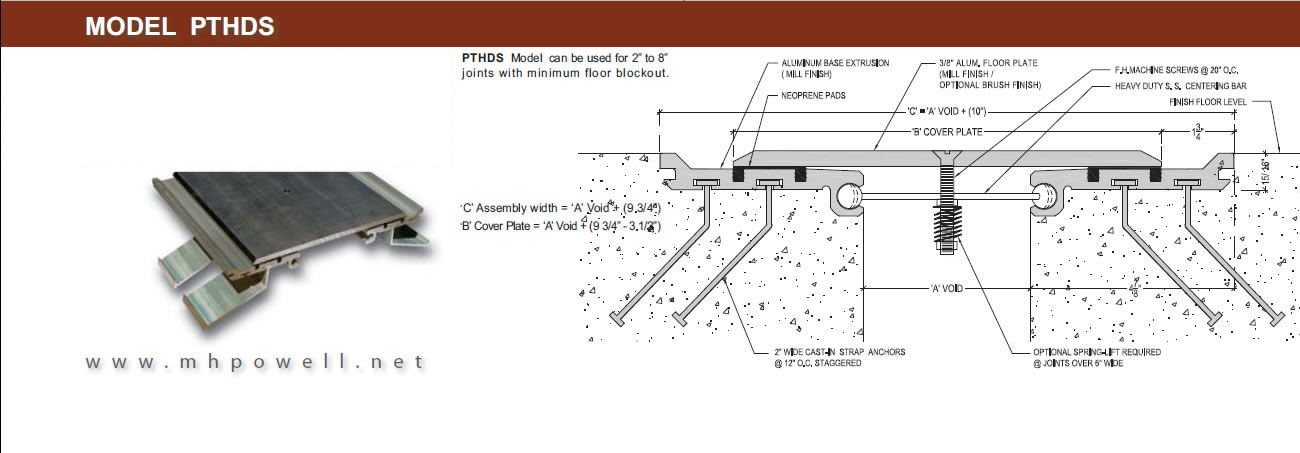
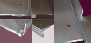
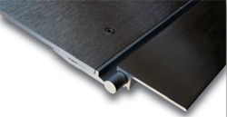
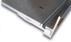
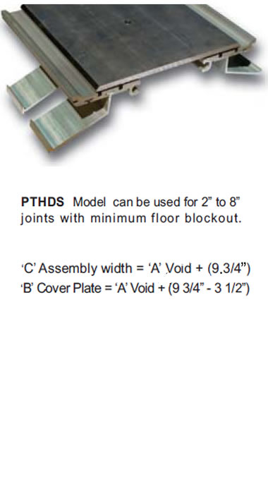
Model PTHDS
Model
Installation Guide
Specs
Model
Installation Guide
Vivamus fringilla suscipit justo
Aenean dui nulla, egestas sit amet auctor vitae, facilisis id odio. Donec dictum gravida feugiat.
Class aptent taciti sociosqu ad litora torquent per conubia nostra, per inceptos himenaeos. Cras pretium elit et erat condimentum et volutpat lorem vehicula
Morbi tincidunt pharetra orci commodo molestie. Praesent ut leo nec dolor tempor eleifend.
W-Series offers wide range of seismic expansion movements.
Custom designed Aluminum cover plates provide the ability to withstand up to 100% or more maximum seismic joint movement.
Specs
| Joint "A" | Model | Max Opening | “B” Cover | Downloads |
| 2"(25.40) | PTHDS-2 | +/-50%(1") | 8.25"(209.55) | PDFCAD |
| 3"(50.80) | PTHDS-3 | +/-50% (1.5") | 9.25"(234.95) | PDFCAD |
| 4"(101.60) | PTHDS-4 | +/-50%(2") | 10.25"(260.35) | PDFCAD |
| 5"(127.00) | PTHDS-5 | +/-50%(2.5") | 11.25"(285.75) | PDFCAD |
| 6"(152.40) | PTHDS-6 | +/-50%(3") | 12.25"(311.15) | PDFCAD |